An HVAC takeoff is the list of everything on the mechanical drawings that has to be bought and installed: the equipment, the air devices at the ceiling, and the duct and pipe that connect them. Estimators build it from the mechanical sheets and the equipment schedules, then price it for material and labor. Electrical contractors build their own version from the same sheets, because every powered unit needs a circuit, a disconnect switch and often controls.
What an HVAC takeoff covers
A complete HVAC takeoff has four parts, and each one is counted or measured differently.
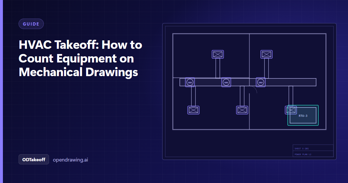
- Equipment. Rooftop units (RTUs), air handling units (AHUs), variable air volume (VAV) boxes, fan coil units, exhaust fans, unit heaters, pumps, and anything else with a tag. These are counts, one line per unique model or size.
- Air devices. Supply diffusers, return grilles, exhaust registers and linear slots, counted by type and neck size. A typical office floor can have more air devices than every other item on the mechanical sheets combined.
- Ductwork. The duct takeoff: lengths by size and shape (rectangular, round, flex), fittings such as elbows, transitions and reducers, hangers, insulation or lining, and accessories like volume dampers, fire dampers and access doors.
- Piping. Hydronic, refrigerant and condensate piping measured by system and size, plus valves, strainers, and specialties at each coil and pump.
Equipment and air devices are counts. Duct and pipe are lengths. That split matters later when you decide what software can do for you.
Takeoff fittings, the other meaning of HVAC takeoff
On site, a takeoff is also a fitting: the collar that connects a branch duct to a trunk duct. A round takeoff with a damper feeds one diffuser and lets the balancer set its airflow. A saddle takeoff straps onto a round trunk, and a rectangular takeoff is cut into a rectangular trunk, sometimes with a scoop that turns air into the branch. These fittings are rarely tagged, so count one per branch and check the total against the air device count.
Reading the mechanical sheets and the equipment schedules
Sheet numbering varies by firm, but most mechanical sets follow a similar order. The first sheet (often M0.01 or M-001) carries the legend, abbreviations and general notes. Plan sheets follow, usually split into ductwork plans and piping plans per floor, then a roof plan, then details, then the schedules.
Start with the legend. It tells you how this engineer draws a supply diffuser, a fire damper or a VAV box, and the project legend overrides any generic chart you have memorized. Our guide to HVAC and mechanical drawing symbols covers the common conventions and where sets tend to differ.
Next, go to the schedules before you count anything. The equipment schedule is the source of truth for what each tag means. A rooftop unit schedule row typically carries the tag (RTU-1), the area served, supply airflow in cubic feet per minute (CFM), cooling and heating capacity, electrical data (voltage, phase, minimum circuit ampacity (MCA) and maximum overcurrent protection (MOCP)), operating weight, and remarks such as "provide with factory-mounted disconnect" or "provide with economizer."
Then count tags on the plans and reconcile them against the schedule:
- Every tag on the plans should have a schedule row, and every schedule row should appear somewhere on the plans.
- Watch for "typical" notes. One VAV box drawn with "TYP OF 12" (typical of 12) is twelve boxes.
- Check the roof plan against the floor plans. Rooftop equipment is sometimes shown on both, and counting it twice is an easy mistake.
- Read the general notes and the specification sections on who furnishes what. Starters, variable frequency drives (VFDs), disconnects and control wiring move between specification divisions (Division 23 for HVAC, Division 26 for electrical) from job to job.
Equipment types and what they mean for each trade
This table covers the equipment you will see most often and how it splits between mechanical and electrical scope. Always confirm the split against the notes and the responsibility matrix on your job.
| Equipment | Typical tag | Mechanical scope | Electrical scope |
|---|---|---|---|
| Rooftop unit | RTU-1 | Unit, curb, duct connections, gas piping if gas heat, condensate | Feeder (the power run from the panel) sized from MCA and MOCP, disconnect within sight, service receptacle, controls as noted |
| Air handling unit | AHU-1 | Unit, coils, piping to coils, duct connections, filters | Feeder, disconnect, VFD power if the fan is variable speed, controls as noted |
| VAV box | VAV-2-14 | Terminal unit, inlet duct, reheat coil piping if hydronic | Power circuit if reheat is electric, controller power if scoped to Division 26 |
| Fan coil unit | FCU-3 | Unit, piping, condensate, duct or grille connections | Branch circuit, local disconnect or switch, thermostat wiring as noted |
| Exhaust fan | EF-4 | Fan, curb or wall cap, duct connection, backdraft damper | Branch circuit, disconnect, interlock or switch control as noted |
| Unit heater | UH-2 | Unit, hanger, piping if hot water or steam | Branch circuit, disconnect, thermostat wiring if electric or fan powered |
| Pump | P-1 | Pump, valves, strainer, piping, pressure gauges | Motor feeder, disconnect, starter or VFD as noted |
The VAV row is where the counts climb: a two-story office with six rooftop units can easily have 40 VAV boxes.
The electrical contractor's side of the mechanical drawings
For an electrical estimator, the mechanical sheets are a second set of power plans that the electrical engineer may or may not have fully reflected on the electrical sheets. The National Electrical Code (NEC) generally requires a disconnecting means within sight of HVAC equipment, so each RTU, condensing unit and exhaust fan is at least a disconnect, a feeder and a set of terminations. The electrical data in the mechanical schedule (MCA, MOCP, voltage and phase) sizes the wire and the breaker.
The cross-check is straightforward. List every powered tag from the mechanical schedules, then find each one on the electrical plans and in a panel schedule. Anything without a circuit is either a coordination gap to raise in a request for information (RFI) or scope you need to price anyway. The load description column on each panel schedule is where that match usually shows up, as "RTU-1" or "EF-4" next to a breaker.
Control wiring deserves its own line. On many jobs the controls contractor wires thermostats, sensors and VAV controllers under Division 23. On others, some of that work, or the 120V power to control panels, lands in Division 26. The notes decide it, and they are worth reading twice.
What to look for in HVAC takeoff software
HVAC estimating software tends to fall into two groups: measuring tools where a person clicks every item, and automated tools that try to find items on their own. The useful question is which parts of the takeoff each one actually handles.
Equipment and air device counts are a good fit for automation. The tags and symbols are repetitive, and a model that has read the legend first can find them across every sheet. Lengths are a different problem. Duct and pipe runs overlap, change size mid-run, and disappear behind notes, so a measured length you trust still comes from a person.
ODTakeoff is built around that split. It counts rooftop units, air handlers, VAV boxes, fans and other tagged equipment across the mechanical drawings automatically, and your estimators measure duct, pipe and conduit runs by hand with built-in tools in the same review screen. It works with legend extraction, so the model reads the mechanical legend first and only looks for what is listed. The HVAC and mechanical takeoff release has the details. Every count is reviewed and corrected by your team before it goes into a bid.
We do not hand you a generic tool. We sit with your estimators to learn how your shop builds a mechanical or electrical bid, then fine-tune our models and add rules for your symbols, your scope and your part numbers, or train a new model on your own drawings when the job calls for it. The export lands in your estimating system or enterprise resource planning (ERP) system in the format you already use. For a plain explanation of what the model does on each page, see how AI takeoff software works.
If your firm also keeps decades of mechanical as-built drawings for building owners, ODRecords turns those paper sets into a searchable archive. Contractors who do work for municipal utilities may run into ODMaps, which turns paper network maps into geographic information system (GIS) maps.
To set up ODTakeoff around your mechanical takeoffs, talk to an expert about a custom deployment.