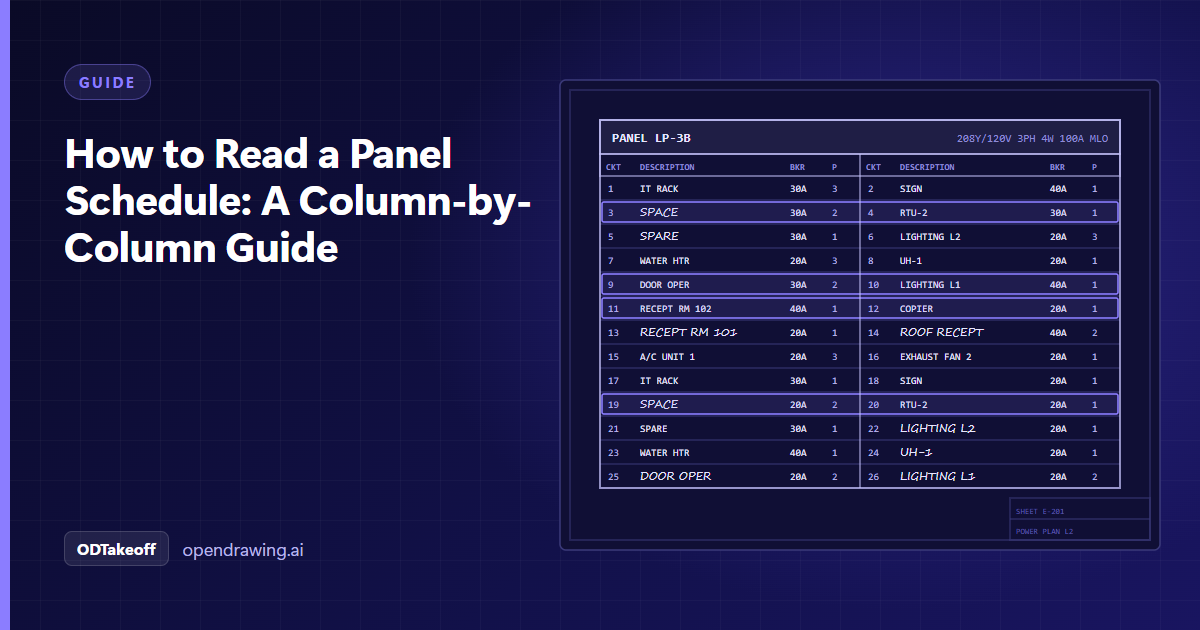
A panel schedule, often called an electrical panel schedule, is the table on an electrical drawing that describes one panelboard, load center or switchboard. The header gives the panel name, voltage, phase, wires, bus rating, main breaker or main lugs only (MLO), mounting and amps interrupting capacity (AIC) rating; each row below lists a circuit with its number, description, breaker trip, poles and load in volt-amperes (VA). Totals at the bottom show the connected load per phase and for the whole panel.
Most commercial sets have one schedule per panel, usually on a sheet near the back of the electrical drawings, often numbered in the E-600 or E-700 series. A building with 20 panels means 20 schedules, and each one feeds the takeoff, the gear quote and the coordination with every trade that needs power.
The panel schedule header
The header is the part manufacturers care about first. It defines the panelboard itself before a single circuit is listed.
| Header field | Example | What it tells you |
|---|---|---|
| Panel name | LP-2A (lighting panel 2A) | The tag that ties the schedule to the plan symbol and the riser diagram. |
| Voltage | 120/208V | Line-to-neutral and line-to-line voltage. 277/480V panels are usually lighting and mechanical loads. |
| Phase and wires | 3 phase, 4 wire | Three phases plus a neutral. Single phase panels show 1 phase, 3 wire. |
| Bus rating | 100A | The current rating of the bus bars. |
| Main device | MLO, or 100A main breaker | Main lugs only means the feeder (the cable from the upstream panel) lands on lugs and the upstream breaker protects the panel. |
| Mounting | Surface or flush | Changes the enclosure, trim and installation labor. |
| AIC rating | 10,000 AIC | Short-circuit interrupting rating the breakers must meet. |
| Fed from | MDP (main distribution panel) | The upstream panel or switchboard, which tells you where the feeder comes from. |
Some schedules add enclosure type (NEMA 1 for indoor or NEMA 3R for outdoor enclosures), neutral rating, ground bar and notes on surge protection or feed-through lugs. Read the notes under the table too; that is where engineers hide requirements like "provide lockable handle on circuits 7, 9, 11."
Circuit rows and the split A/B layout
Below the header, each row is one circuit. Most commercial schedules use the split layout: odd circuits on the left, even circuits on the right, matching the physical panel. Reading across a row gives two circuits that sit on the same phase. On a three phase panel, the rows cycle A, B, C. On a single phase, 3 wire panel (120/240V) they alternate between A and B only, so circuits 1 and 3 land on different legs and a two pole breaker spans both.
| Column | What it holds | Estimator takes | Manufacturer takes |
|---|---|---|---|
| Circuit number | 1, 3, 5 on the left; 2, 4, 6 on the right | Home run labels on the plans (the wiring run back to the panel) | Breaker position |
| Description | "Receptacles Rm 101", "RTU-1" (rooftop unit 1) | Scope check against the plans and mechanical schedule | Nothing, usually |
| Breaker trip | 20A, 30A | Wire size for the branch circuit | Breaker rating to quote |
| Poles | 1, 2 or 3 | Conductor count | Breaker type and space used |
| Load (VA) | 720, 2,400 | Load check, rarely priced directly | Nothing, usually |
| Phase | A, B or C | Balance check | Nothing, usually |
| Notes or codes | GFCI (ground-fault circuit interrupter), AFCI (arc-fault circuit interrupter), shunt trip, lock-on | Special breakers and devices | Breaker options to quote |
Spares and spaces matter. A spare has a breaker installed with nothing connected, so it is priced. A space is an empty position with no breaker. Mixing the two is a common reason two quotes for the same panel don't match.
A worked panel schedule example
Here is a small, made-up schedule for panel LP-2A: 120/208V, 3 phase, 4 wire, 100A bus, MLO, 10,000 AIC, surface mounted, fed from MDP. Breakers are written as trip/poles, so 20/1 is a 20A single pole breaker.
| Circuit | Description | VA | Breaker | Phase | Breaker | VA | Description | Circuit |
|---|---|---|---|---|---|---|---|---|
| 1 | Receptacles Rm 101 | 720 | 20/1 | A | 20/1 | 900 | Lighting Rm 101 to 104 | 2 |
| 3 | Receptacles Rm 102 | 540 | 20/1 | B | 20/1 | 1,080 | Lighting corridor | 4 |
| 5 | Copier Rm 105 | 1,500 | 20/1 | C | 20/1 | 1,200 | Exterior lighting | 6 |
| 7 | RTU-1 | 2,400 | 30/3 | A | 20/1 | 0 | Spare | 8 |
| 9 | RTU-1 | 2,400 | B | Space | 10 | |||
| 11 | RTU-1 | 2,400 | C | Space | 12 |
Totals: phase A 4,020 VA, phase B 4,020 VA, phase C 5,100 VA, 13,140 VA connected.
From this one schedule, an estimator gets eight breakers (seven single pole including the spare, one three pole), seven circuits to trace back to home runs on the plans, and a reminder that RTU-1 needs a disconnect switch and feeder that may only appear on the mechanical sheets. A manufacturer gets a 100A, 120/208V MLO panel, surface mounted, 10,000 AIC, with six 20A single pole breakers, one 20A single pole spare and one 30A three pole breaker.
Phase balancing and panel totals
Each phase total is the sum of the loads on that phase. In the example, phase C carries about 1,000 VA more than A or B. Engineers try to keep phases within a reasonable spread, and a lopsided schedule is often a sign that a circuit was added late in design.
Many schedules go one step further than connected load. They apply demand factors by load type (lighting, receptacles, motors, kitchen equipment) under the load calculation rules in NEC (National Electrical Code) Article 220, and show a calculated demand load and the minimum feeder size below the totals. Connected load is everything that could run at once; demand load is what the engineer expects to run, and it is the number the feeder and main are sized from.
For estimating, the totals are a sanity check more than a priced item. If the total connected load looks high for a 100A bus, flag it as an RFI (request for information) before bid day. For the manufacturer, totals and demand loads help confirm the bus and main sizes on the header.
Panel schedule templates, directories and real drawings
People search for an electrical panel schedule template because they need a clean table to type into. Free templates in spreadsheet, word processor or PDF form all carry the same header, circuit columns and totals described above. Don't confuse the schedule with the panel directory, the circuit card inside the panel door that labels each breaker for whoever works on it later; NEC 408.4 requires every circuit to be legibly identified there. The template is the easy part. The hard part is getting the data out of the drawings: dense schedules on scanned sheets, handwritten descriptions on older sets, and 20 panels to retype before anyone can check the totals.
ODTakeoff handles that step with panel schedule extraction. It reads every circuit on single and split A/B schedules, typed or handwritten, from CAD exports or scans, and returns circuit, breaker, poles, load and panel totals as rows with the panel name on every line. Your team reviews and corrects the rows before they go into a bid, and the whole drawing set exports to one file in the format your estimating system or enterprise resource planning (ERP) system expects.
We set each deployment up around the customer. That means learning how your team reads schedules, fine-tuning our models and adding rules for your layouts and part numbers, or training a new model on your own drawings when the layout is unusual. There is no generic version to switch on; every account is custom.
The schedule pairs with the plan sheets, so it helps to know the electrical drawing symbols that tie each circuit to a device, and what goes into a complete electrical bill of materials.
Utilities and owners with older panel and one-line drawings in paper files can use ODRecords to make those archives searchable, and utilities mapping their distribution grid from paper records use ODMaps.
To set up panel schedule extraction for your own drawings, talk to an expert.